AGIPD, LPD & DSSC Geometry
Note
This part of karabo_data has been renamed to EXtra-geom. Please use that package in new code.
The AGIPD and LPD detectors are made up of several sensor modules,
from which separate streams of data are recorded.
Inspecting or processing data from these detectors therefore depends on
knowing how the modules are arranged. The module karabo_data.geometry2
handles this information.
All the coordinates used in this module are from the detector centre. This should be roughly where the beam passes through the detector. They follow the standard European XFEL axis orientations, with x increasing to the left (looking along the beam), and y increasing upwards.
Note
This module includes methods to assemble data into a single array. This is sufficient for a quick examination of detector images, but the detector pixels may not line up with the grid imposed by a single array. For accurate analysis, it’s best to use a tool that can process geometry internally with sub-pixel precision.
AGIPD-1M
AGIPD-1M consists of 16 modules of 512×128 pixels each. Each module is further subdivided into 8 tiles. The layout of tiles within a module is fixed by the manufacturing process, but this geometry code works with a position for each tile.
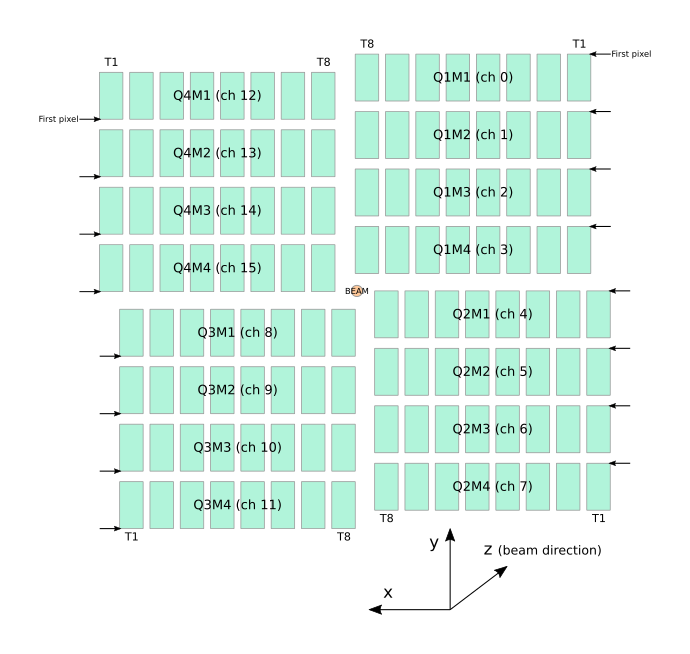
The approximate layout of AGIPD-1M, in a front view (looking along the beam).
LPD-1M
LPD-1M consists of 16 supermodules of 256×256 pixels each. Each supermodule is further subdivided into 16 sensor tiles, which this geometry code can position independently.
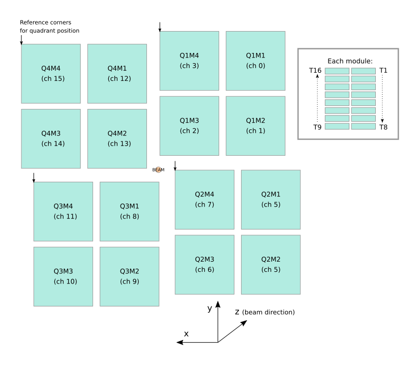
The approximate layout of LPD-1M, in a front view (looking along the beam).
DSSC-1M
DSSC-1M consists of 16 modules of 128×512 pixels each. Each module is further subdivided into 2 sensor tiles, which this geometry code can position independently.
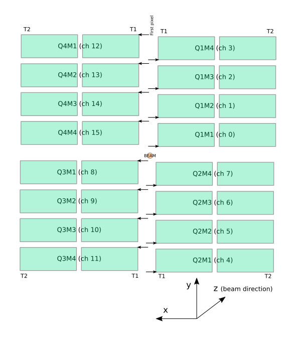
The approximate layout of DSSC-1M, in a front view (looking along the beam).
The pixels in each DSSC module are tesselating hexagons. This geometry code does not yet handle this: it treats the pixels as rectangles to simplify processing. This is adequate for previewing detector images, but some pixels will be approximately half a pixel width from their true position.
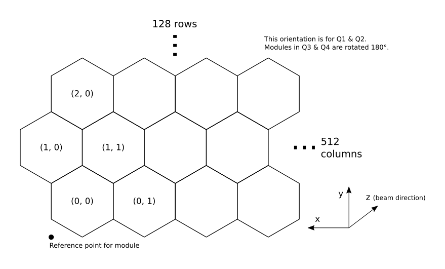
Detail of hexagonal pixels in the corner of one DSSC module.